


SHENZHEN KINRI ENERGY
Huizhou (HK) Yingyuan Technology
Support Hotline
+86 137-2371-6834 Timber (WhatsApp)


Huizhou (HK) Yingyuan Technology
+86 137-2371-6834 Timber (WhatsApp)
Switching power supply, also known as switching power supply or switching converter, is a high-frequency electrical energy conversion device and a type of power supply. Its function is to convert a precise voltage into the voltage or current required by the user through different forms of architecture. The input of a switching power supply is mostly AC or DC power, while the output is mostly for devices that require DC power, such as personal computers, and the switching power supply converts voltage and current between the two.
Catalogue
1. Introduction to Power Supply
2. Main applications
3. Main types
4. Basic composition
5. Main categories
6. Development direction
7. Working principle
8. Main features
9. Working mode
1.Introduction to Power Supply
Switching power supplies are different from linear power supplies. The switching transistors used in switching power supplies mostly switch between fully open mode (saturation zone) and fully closed mode (cutoff zone), both of which have the characteristic of low dissipation. The conversion between switches will have high dissipation, but the time is short, so it is more energy-efficient and produces less waste heat. Ideally, switch mode power supplies themselves do not consume electrical energy. Voltage stabilization is achieved by adjusting the time of transistor conduction and disconnection. On the contrary, in the process of generating output voltage in a linear power supply, the transistor operates in the amplification region and consumes electrical energy itself. The high conversion efficiency of switch mode power supplies is one of its major advantages, and due to their high operating frequency, small and lightweight transformers can be used. Therefore, switch mode power supplies are smaller in size and lighter in weight than linear power supplies.
If the high efficiency, volume, and weight of the power supply are the key considerations, switch mode power supply is better than linear power supply. However, switch mode power supplies are relatively complex, with frequent switching of internal transistors. If the switching current is not processed, it may generate noise and electromagnetic interference that affects other devices. Moreover, if the switch mode power supply is not specially designed, its power factor may not be high.
2.Main applications
Switching power supply products are widely used in industrial automation control, military equipment, scientific research equipment, LED lighting, industrial control equipment, communication equipment, power equipment, instruments and meters, medical equipment, semiconductor refrigeration and heating, air purifiers, electronic refrigerators, LCD displays, LED lighting fixtures, communication equipment, audio-visual products, security monitoring, LED light strips, computer cases, digital products and instruments, and other fields.
3.Main types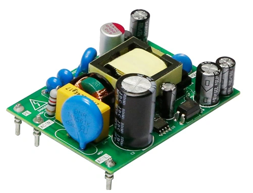
There are two types of modern switching power supplies: one is DC switching power supplies; Another type is AC switching power supply. The main focus here is on DC switching power supplies, which function to convert raw power sources (such as mains power or battery power) with poor power quality into high-quality DC voltage (precision power) that meets equipment requirements. The core of a DC switching power supply is a DC/DC converter. Therefore, the classification of DC switching power supplies depends on the classification of DC/DC converters. That is to say, the classification of DC switching power supplies is basically the same as the classification of DC/DC converters, and the classification of DC/DC converters is basically the classification of DC switching power supplies.
DC/DC converters can be divided into two categories based on whether there is electrical isolation between input and output: one type is called isolated DC/DC converters; Another type is called non isolated DC/DC converters without isolation.
Isolated DC/DC converters can also be classified according to the number of active power devices. There are two types of single tube DC/DC converters: forward and flyback. There are four types of dual transistor DC/DC converters: Double Transistor Forward Converter, Double Transistor Flyback Converter, Push Pull Converter, and Half Bridge Converter. A four tube DC/DC converter is a full bridge DC/DC converter.
Non isolated DC/DC converters can be classified into three types based on the number of active power devices: single transistor, double transistor, and four transistor. There are six types of single tube DC/DC converters, namely Buck DC/DC converter, Boost DC/DC converter, Buck Boost DC/DC converter, Cuk DC/DC converter, Zeta DC/DC converter, and SEPIC DC/DC converter. Among these six types of single tube DC/DC converters, Buck and Boost type DC/DC converters are basic, and Buck Boost, Cuk, Zeta, and SEPIC type DC/DC converters are derived from them. The dual tube DC/DC converter has a Buck Boost DC/DC converter with dual tube serial connection. The commonly used four tube DC/DC converter is a Full Bridge DC/DC converter.
Isolation type DC/DC converters usually use transformers to achieve electrical isolation between output and input. Due to the transformer's transformer function, it is beneficial to expand the output application range of the converter and facilitate the realization of multiple outputs of different voltages or multiple outputs of the same voltage.
When the voltage and current ratings of power switching tubes are the same, the output power of the converter is usually proportional to the number of switching tubes used. So the more switching tubes there are, the higher the output power of the DC/DC converter. The output power of the four tube type is twice that of the two tube type, while the output power of the single tube type is only 1/4 of that of the four tube type.
The combination of non isolated and isolated converters can obtain some characteristics that a single converter does not possess.
DC/DC converters can also be divided into self-excited and externally controlled types. A converter that utilizes the positive feedback signal of the converter itself to achieve self sustained periodic switching of the switching tube is called a self-excited converter, such as a typical push-pull self-excited converter. The control signal of the switching device in the controlled DC/DC converter is generated by an external specialized control circuit.
According to the switching conditions of the switching tube, DC/DC converters can be divided into two types: hard switching and soft switching. The switching device of a hard switching DC/DC converter turns on or off the circuit under voltage or current flow, resulting in significant overlap loss, also known as switching loss. When the working state of the converter is constant, the switching loss is also constant, and the higher the switching frequency, the greater the switching loss. At the same time, during the switching process, it will also cause oscillations in the distributed inductance and parasitic capacitance of the circuit, resulting in additional losses. Therefore, the switching frequency of a hard switching DC/DC converter cannot be too high. The switching transistor of a soft switching DC/DC converter is either zero voltage switching (ZVS) when turned on or off, or zero current switching (ZCS) when the current passing through the transistor is zero. This soft switching method can significantly reduce switching losses and oscillations generated during the switching process, allowing for a significant increase in switching frequency and creating conditions for miniaturization and modularization of the converter. Power field-effect transistor (MOSFET) is a widely used switching device, which has a high switching speed but also has a large parasitic capacitance. When it is turned off, under the action of external voltage, its parasitic capacitance is fully charged. If this part of the charge is not discharged before it is turned on, it will be consumed inside the device, which is called capacitive turn-on loss. To reduce or eliminate this loss, it is advisable to use zero voltage turn-on (ZVS) for power field-effect transistors.Insulated Gate Bipolar Transistor (IGBT) is a composite switching device. The trailing current during turn off can cause significant turn off losses. If the current flowing through it is reduced to zero before turn off, it can significantly reduce switch losses. Therefore, IGBT should adopt zero current (ZCS) turn off mode. IGBT can also reduce turn off losses under zero voltage conditions, but MOSFETs cannot reduce capacitive turn on losses when turned on under zero current conditions. Resonant Converter (RC), Quasi Resonant Converter (QRC), Multi Resonant Converter (MRC), Zero Voltage Switching PWM Converter (ZVS PWM Converter), Zero Current Switching PWM Converter (ZCS PWM Converter), Zero Voltage Transition (ZVT) PWM Converter, and Zero Voltage Transition (ZVT) PWM Converter, etc, All belong to soft switching DC converters. The development of power electronic switching devices and zero switching converter technology has promoted the development of high-frequency switching power supplies.
4.Basic composition
The switch power supply is roughly composed of four main parts: the main circuit, control circuit, detection circuit, and auxiliary power supply.
1. Main circuit
Impulse current limiting: limits the impulse current on the input side at the moment the power is turned on.
Input filter: Its function is to filter out the clutter existing in the power grid and feedback the clutter that hinders the generation of the machine back to the power grid.
Rectification and filtering: Directly rectifying the AC power supply of the power grid into smoother DC power.
Inversion: Transforming rectified DC power into high-frequency AC power, which is the core part of high-frequency switching power supplies.
Output rectification and filtering: Provide stable and reliable DC power supply according to load requirements.
2. Control circuit
On the one hand, samples are taken from the output end, compared with the set value, and then the inverter is controlled to change its pulse width or frequency to ensure stable output. On the other hand, based on the data provided by the test circuit and identified by the protection circuit, control circuits are provided to provide various protection measures for the power supply.
3. Detection circuit
Provide various parameters and instrument data that are currently in operation in the protection circuit.
4. Auxiliary power supply
Implement software (remote) startup of the power supply to provide power for the protection circuit and control circuit (PWM and other chips).
5.Main categories
In the field of switch mode power supply technology, people are developing related power electronic devices and switch frequency conversion technology at the same time. The two mutually promote the development of switch mode power supplies with a growth rate of over two digits each year towards the direction of light, small, thin, low noise, high reliability, and anti-interference. Switching power supplies can be divided into two categories: AC/DC and DC/DC.
Micro Low Power Switching Power Supply
Switching power supplies are moving towards popularization and miniaturization. Switching power supplies will gradually replace transformers in all applications in daily life. The application of low-power micro switching power supplies should first be reflected in digital display meters, smart meters, mobile phone chargers, and other aspects. At present, the country is vigorously promoting the construction of smart grids, and the requirements for energy meters are greatly increased. Switching power supplies will gradually replace transformers in the application of energy meters.
Reverse series switching power supply
The difference between a reverse series switching power supply and a general series switching power supply is that the output voltage of this reverse series switching power supply is negative, which is exactly opposite to the polarity of the positive voltage output of a general series switching power supply; And because the energy storage inductor L only outputs current to the load when the switch K is turned off, under the same conditions, the output current of the reverse series switching power supply is twice that of the series switching power supply.
6.Development Direction
The high-frequency of switching power supplies is the direction of its development. High frequency makes switching power supplies miniaturized and enables them to enter a wider range of application fields, especially in high-tech fields, driving the development of switching power supplies. Every year, with a growth rate of more than two digits, it develops towards the direction of light, small, thin, low noise, high reliability, and anti-interference. Switching power supplies can be divided into two categories: AC/DC and DC/DC. DC/DC converters have now achieved modularization, and the design technology and production process have become mature and standardized both domestically and internationally, and have been recognized by users. However, the modularization of AC/DC, due to its own characteristics, encounters complex technical and manufacturing problems in the process of modularization. In addition, the development and application of switch mode power supplies are of great significance in energy conservation, resource conservation, and environmental protection.
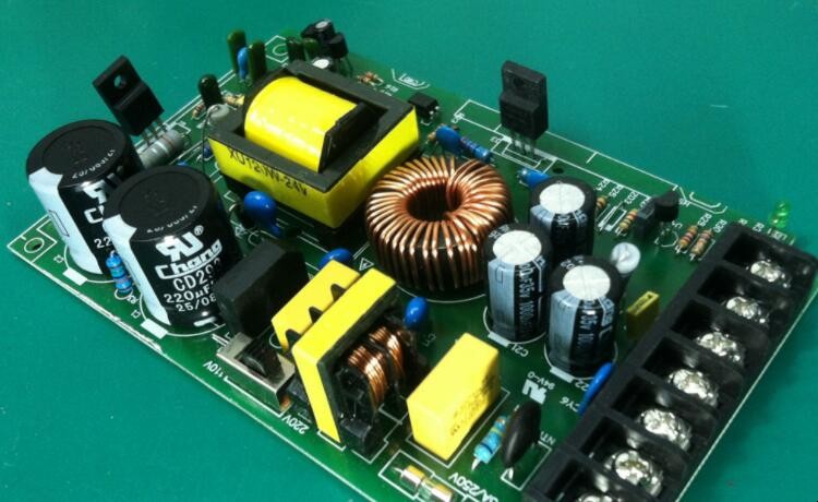
The power electronic devices used in switch mode power supplies mainly include diodes, IGBTs, MOSFETs, and transformers.
SCR has a small number of applications in input rectifier circuits and soft start circuits of switching power supplies. GTR is difficult to drive and has low switching frequency, gradually being replaced by IGBT and MOSFET.
The development direction of switch mode power supplies is high frequency, high reliability, low consumption, low noise, anti-interference, and modularization. Due to the key technology of lightweight, small, and thin switching power supplies being high-frequency, major foreign switching power supply manufacturers are committed to synchronously developing new types of highly intelligent components, especially improving the losses of secondary rectification devices, and increasing technological innovation in power ferrite materials to improve the acquisition of high magnetic properties at high frequencies and large magnetic flux densities (Bs). The miniaturization of capacitors is also a key technology. The application of SMT technology has made significant progress in switch mode power supplies, by arranging components on both sides of the circuit board to ensure the lightness, small size, and thinness of switch mode power supplies. The high-frequency of switching power supplies will inevitably innovate traditional PWM switching technology, and achieving soft switching technology of ZVS and ZCS has become the mainstream technology of switching power supplies, greatly improving the working efficiency of switching power supplies. For high reliability indicators, American switch mode power supply manufacturers take measures such as reducing operating current and junction temperature to reduce device stress, greatly improving product reliability.
Modularization is the overall trend in the development of switch mode power supplies. Modular power supplies can be used to form a distributed power supply system, which can be designed as an N+1 redundant power supply system and achieve capacity expansion in parallel. In response to the drawback of high operating noise in switch mode power supplies, if high-frequency conversion is pursued alone, the noise will inevitably increase. However, using partial resonant conversion circuit technology can theoretically achieve high-frequency conversion and reduce noise. However, there are still technical problems in the practical application of some resonant conversion technologies, so a lot of work needs to be carried out in this field to make this technology practical.
The continuous innovation of power electronics technology has given the switching power supply industry broad development prospects. To accelerate the development speed of China's switching power supply industry, it is necessary to take the path of technological innovation and embark on a path of joint development of industry, academia, and research with Chinese characteristics, making contributions to the rapid development of China's national economy.
7.Operational Principle
The working process of a switching power supply is quite easy to understand. In a linear power supply, the power transistor is operated in linear mode. Unlike linear power supplies, PWM switching power supplies operate the power transistor in both on and off states. In these two states, the volt ampere product added to the power transistor is very small (when it is on, the voltage is low, the current is high; when it is off, the voltage is high, the current is small) /The volt ampere product on power devices is the loss generated on power semiconductor devices.
Compared with linear power supplies, the more effective working process of PWM switching power supplies is achieved through "chopping", which chops the input DC voltage into a pulse voltage with an amplitude equal to the input voltage amplitude. The duty cycle of the pulse is adjusted by the controller of the switching power supply. Once the input voltage is chopped into an AC square wave, its amplitude can be increased or decreased through a transformer. By increasing the number of secondary windings in the transformer, the output voltage value can be increased. Finally, these AC waveforms are rectified and filtered to obtain a DC output voltage.
The main purpose of the controller is to maintain stable output voltage, and its working process is similar to that of a linear controller. That is to say, the functional blocks, voltage reference, and error amplifier of the controller can be designed to be the same as linear regulators. Their difference is that the output of the error amplifier (error voltage) needs to go through a voltage/pulse width conversion unit before driving the power transistor.
Switching power supplies have two main operating modes: forward conversion and boost conversion. Although the differences in the arrangement of their respective parts are small, the working processes vary greatly and each has its own advantages in specific application scenarios.
8.Main Features
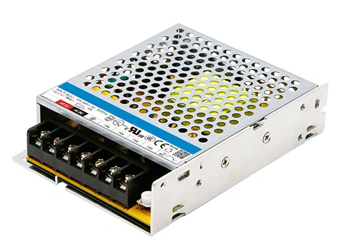
1. Small size and light weight: Due to the absence of a power frequency transformer, the volume and weight are only 20-30% of those of linear power sources.
2. Low power consumption and high efficiency: The power transistor operates in a switching state, so the power consumption on the transistor is low and the conversion efficiency is high, usually 60-70%, while linear power supplies only have 30-40%.
3. Simple structure and high reliability: easy to maintain, and the current ripple rate can be easily reduced.
9.Working Mode
As the name suggests, a switching power supply is the use of electronic switching devices (such as transistors, field-effect transistors, thyristors, etc.) to continuously "turn on" and "turn off" the electronic switching devices through a control circuit, allowing them to pulse modulate the input voltage, thereby achieving DC/AC, DC/DC voltage conversion, and adjustable automatic voltage stabilization of the output voltage.
Switching power supplies generally have three operating modes: fixed frequency and pulse width mode, fixed frequency and variable pulse width mode, and variable frequency and pulse width mode. The former working mode is often used for DC/AC inverter power supplies or DC/DC voltage conversion; The latter two working modes are mostly used for switch regulated power supplies. In addition, there are three working modes for the output voltage of switch mode power supplies: direct output voltage mode, average output voltage mode, and amplitude output voltage mode. Similarly, the former working method is often used for DC/AC inverter power supplies or DC/DC voltage conversion; The latter two working methods are mostly used for switch regulated power supplies.
According to the way switching devices are connected in the circuit, switching power supplies can generally be divided into three categories: series switching power supplies, parallel switching power supplies, and transformer switching power supplies. Among them, transformer switching power supplies can be further divided into various types, such as push-pull, half bridge, full bridge, etc; According to the excitation of the transformer and the phase of the output voltage, it can be further divided into various types: forward excitation, flyback, single excitation, and double excitation; If divided by purpose, it can also be divided into more types.

Scan And Follow Us
 Phone:+86-+86 137-2371-6834 Timber (WhatsApp)
 Tel:+86-0755-29665062
 Email:mkt1@jinruipower.com
 Add: No. 13A16 Huafeng International Commercial Building, No.4018 Bao’an Avenue, Xixiang, Baoan District, Shenzhen China

 Alibaba
 0755-29665062
 Online Service