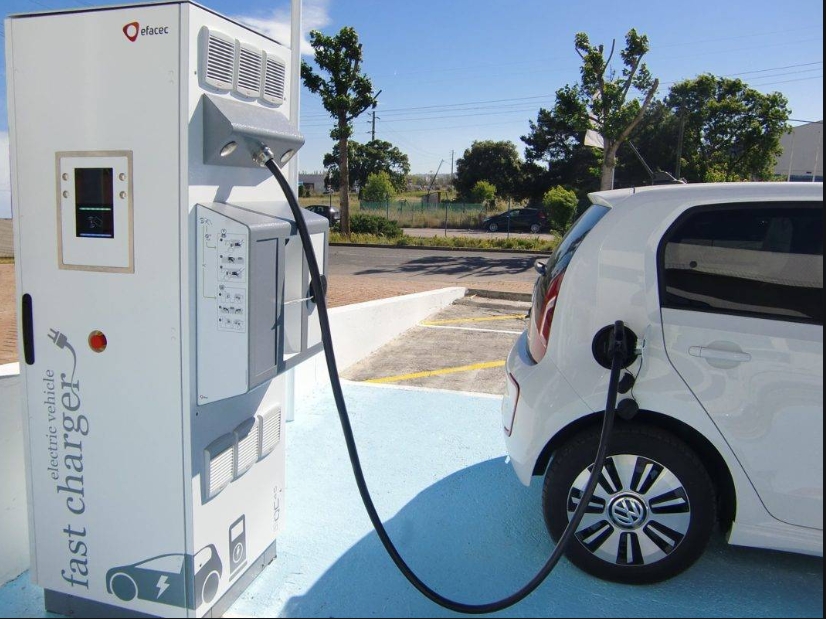
Charging time is a major consideration for consumers and businesses when evaluating the purchase of electric vehicles (EVs). In order to shorten charging time, the industry is turning to using DC charging stations (DCFCs). DCFC bypasses the onboard charger of electric vehicles and directly provides higher power to the battery, greatly reducing charging time.In order to achieve faster charging speed, adapt to higher voltage of electric vehicle batteries, and improve overall energy efficiency, DCFCs must operate at higher voltage and power levels. This poses a challenge for OEMs, as they must design an architecture that can optimize efficiency without compromising reliability and security.DCFC integrates multiple devices, including those used for auxiliary power supply, sensing, power management, connection, and communication. In addition, in order to meet the constantly evolving charging needs of various electric vehicles, flexible manufacturing methods must be adopted, which also makes the design more complex.
Figure 1 Overview of the main modules in DCFC
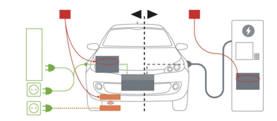
Fast and ultra fast chargingFigure 2 shows the difference between AC charging and DC charging. For AC charging (left side of Figure 2), the onboard charger (OBC) is plugged into a standard AC socket. OBC converts alternating current into appropriate direct current to charge the battery. For DC charging (on the right side of Figure 2), the charging station directly charges the battery.
Figure 2. Conceptual diagram of AC charging and DC charging.
Source: Yol é Development
At present, the OBC of electric vehicles relies on AC charging, with a maximum rated power of 22 kW. DC charging bypasses the OBC and directly delivers DC power to the battery, thus providing much higher power, ranging from 50 kW to over 400 kW or even higher.For this reason, DCFC is often referred to as a "fast" or "ultra fast" charging station. Such high charging speed and greater convenience have brought more applications and use cases for electric vehicles. For example, if an electric vehicle takes eight hours to fully charge, it is not suitable for long-distance driving. However, with the help of ultra fast charging stations, electric vehicles can charge a large amount during short rest periods, increasing the vehicle's range and making it more suitable for daily use. Therefore, from now to 2030, the compound annual growth rate of fast DC charging piles is expected to exceed 30% (source: Yol é Development).The advancement of silicon carbide (SiC) and power integration module (PIM) technology is a key driving force for promoting the transition towards faster charging. SiC enables DCFC to operate at higher frequencies (thus higher efficiency) while providing more power at a faster speed. PIM enables OEMs to quickly integrate advanced technologies into compact and lightweight devices, achieving excellent thermal management, reliability, and manufacturability, thereby accelerating the popularization of SiC technology.Analysis of DCFCAs shown in Figure 3, the DC charging station mainly consists of two levels: AC-DC level and subsequent DC-DC level. The AC-DC level converts AC power from the grid into DC power, while the second level ensures power supply at the voltage and current levels suitable for the battery(Figure 3 Architecture of DCFC).
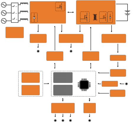
For commercial applications, a Level 3 charging station requires the use of a three-phase power supply (Figure 4), which can increase the range by over 100 miles in just 30 minutes. These ultra fast charging stations will play an important role in introducing electric vehicle technology into transportation and logistics applications.The front end of a 3-stage DCFC consists of a three-phase power factor correction (PFC) boost stage, which can be unidirectional or bidirectional; The boost stage can be implemented using various topologies (two-level or three-level). The PFC level receives grid voltage (400 EU, 480 US) and boosts it to 700 to 1000 V. For the next generation of charging stations, the industry has already targeted higher voltages.After the boost stage, the DC-DC isolation stage converts the bus voltage into the desired output voltage. This voltage needs to be consistent with the charging curve of the electric vehicle battery. Therefore, the DC-DC output may need to oscillate between 150 V and 1500 V, depending on the battery and the charging stage it is in. Converters are typically optimized for specific voltage levels (typically 400 V or 800 V). In order to achieve higher power levels, DCFC will stack multiple power modules and operate them in parallel.In order to achieve higher efficiency under such high voltages, the industry is shifting from discrete, IGBT, and hybrid solutions to SiC power integration modules (PIMs). In addition to PIM, DCFC also requires various power devices, including gate driver ICs, digital isolators, power supply ICs (LDO, SMPS, etc.), and current detection.Communication and connectivity are also key aspects of DCFC design. The stacked modules need to be able to communicate with the charging station controller, and the vehicle and charging station must communicate on the charging sequence (CAN or PLC). An independent fast DC charging station also needs to be able to handle charging related payments. Finally, the charging station needs to manage its own maintenance, software upgrades, etc. (such as through Bluetooth low-power, Wi Fi 4, LTE). The actual standard is determined by the DC charging protocol used, such as IEC 61851/SAE1772, GB/T, CHAdeMO, Combined Charging System (CCS), or Tesla Supercharger Station.
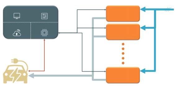
 When designing DCFC, there are multiple key factors to consider, which can affect architecture design and device selection:Target efficiencyDetermine the voltage and power range that should optimize efficiency. The charging station operates at different levels during charging, so the system should be optimized for the level that has the greatest impact on power transmission efficiency.Split type design or power integration module (PIM)The flexibility of the split design is greater, but the development process is also more complex (Figure 7). For many applications, the many efficiency advantages of modules are difficult to achieve in a separate design. For example, modules integrate multiple power devices into a single compact package, simplifying mechanical assembly, optimizing thermal management, improving reliability, and reducing voltage spikes and high-frequency EMI.Architecture/TopologyThe selected topology structure (i.e., two-level or three-level) and whether the charging station needs to operate unidirectionally or bidirectional will all affect the selection of the device. There are many topology options for implementing PFC and DC-DC levels of DC charging stations. Due to the high power and voltage levels, the preferred architecture for many OEMs is generally three-stage power factor correction (PFC). The most commonly used topology structures for PFC design include three switches Vienna (unidirectional), NPC, A-NPC, T-NPC (bidirectional replacement diode), and six switches (bidirectional). The DC-DC level is typically implemented in full bridge or phase shifted LLC and its variants, and adopts a dual active bridge (DAB) architecture to support bidirectional topology. These topologies include two-level and three-level systems, which use 600 to 650 V or 900 to 1200 V switches and diodes, respectively. (Further understanding of topology: Fast DC electric vehicle charging: Common topologies and power devices used in the system)ConstraintsAttention should be paid to physical system constraints, including size, weight, cost, and other limiting factors that need to be considered. For example, if size and weight are important, choosing a SiC based module will reduce overall wiring requirements, reduce system size, and reduce vehicle weight.Thermal managementManaging heat dissipation is crucial for maintaining efficiency, reliability, and system lifespan. Using SiC devices to operate at higher frequencies can increase power density, improve efficiency, and reduce the amount of heat that needs to be managed. In addition, many modules have been optimized for heat transfer using extremely low thermal resistance materials.Simulation modelHaving precise models of devices and modules can greatly simplify and accelerate the design process, especially when weighing multiple design options.CommunicationClarify which standards and protocols are required for specific applications. Ensure that the selected suppliers and product lines support all possible standards that may need to be included to support current and future electric vehicles.ProtectionAccording to regulatory requirements, it is necessary to equip with Ground Fault Interruption (GFI) function. Other functions such as surge current and overvoltage protection are also crucial. How to integrate these functions in the system (i.e. separate circuits, part of power stages, integrated on modules, etc.) will affect the optimization of constraints on other systems.Advanced charging architectureIdeally, electric vehicles should be charged during off peak hours. This will greatly reduce the cost of electricity and reduce the load on the grid during peak hours, avoiding power outages.To achieve this goal, DC charging stations need to be integrated with energy storage systems (ESS) and solar power generation systems. ESS charges during off peak hours to store electricity for daytime use. By installing solar panels to generate electricity during the day, the consumption of ESS electricity can be reduced, thereby reducing the load on ESS. In this configuration, the DC/DC converter can be connected to the high-voltage bus to charge the electric vehicle.summaryBy understanding the key design considerations that affect device selection, engineers can optimize the architecture of high-power DC charging stations to achieve higher efficiency, reliability, and performance. With the advancement of technologies such as silicon carbide and power integration modules, engineers can evaluate and design complex systems more quickly without compromising. As a result, OEM can quickly and economically meet the charging needs of the market. Moreover, OEMs can collaborate with suitable partners to create more sustainable infrastructure by integrating new technologies such as energy storage systems, thereby continuously improving product quality and practicality.Although IGBT and hybrid implementation solutions are still in use, SiC based power modules are rapidly becoming the preferred solution for DCFC charging applications.


 Phone:+86-+86 137-2371-6834 Timber (WhatsApp)
 Tel:+86-0755-29665062
 Email:mkt1@jinruipower.com
 Add: No. 13A16 Huafeng International Commercial Building, No.4018 Bao’an Avenue, Xixiang, Baoan District, Shenzhen China

 Alibaba
 0755-29665062
 Online Service