Welcome to Shenzhen KINRI Energy Technology Co.,Ltd. official website!
Language:

Shenzhen KINRI Energy Technology Co.,Ltd.

SHENZHEN KINRI ENERGY

Huizhou (HK) Yingyuan Technology

Support Hotline

137-2371-6834 Timber (WhatsApp)

Shenzhen KINRI Energy Technology Co.,Ltd.
News
Current Location: Home > News > Company News

News

0755-29665062

Certificate

Shenzhen KINRI Energy Technology Co.,Ltd.
Company News

XINGYU CO., LTD has obtained a patent for a single string LED short circuit detection feedback circuit in a switching power supply, which can realize the design of car lighting circuits

Article Source:Kinri Energy | Author:Kinri Energy | Issuing Time:2024.04.23
On April 23, 2024, the financial sector reported that, according to the announcement of the China National Intellectual Property Administration, Changzhou XINGYU AUTOMOTIVE LIGHTING Co., Ltd. obtained a patent entitled "a single string LED short circuit detection feedback circuit of switching power supply", with the authorization announcement number of CN108575018B, and the application date of August 2017.

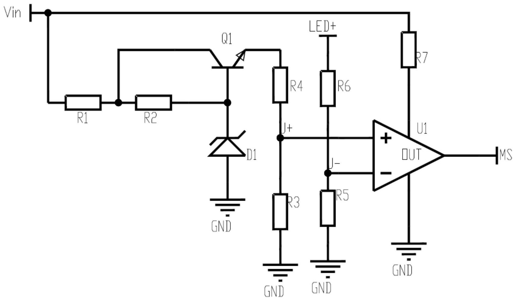
The patent abstract shows that the present invention relates to a design of a car lighting circuit, in particular to a switch power supply single string LED short circuit detection feedback circuit, including a switch power supply driving chip U2 and a driving circuit connected to the driving chip U2. The 15th pin of the driving chip U2 is connected to the drain of the MOS tube Q3, the source of the MOS tube Q3 is grounded, and one end of the resistor R9 is connected. The gate of the MOS tube Q3 is connected to the positive pole of the voltage regulator tube D3, and the other end of the MS end and R9 are connected. The negative pole of the voltage regulator tube D3 is connected to the LED output end, and an additional terminal is added at the input end Vin, LED output end, and MS end of the switch power supply. Comparator U1, the input terminal U+of comparator U1 is connected to one end of resistor R3 and resistor R4 respectively, the other end of resistor R3 is grounded, and the other end of resistor R4 is connected to the emitter of transistor Q1.


Attached drawings of patent abstract