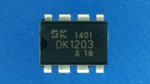
Overview

DK1203 is a flyback secondary side switching power supply control chip. AC-DC switching power supply dedicated to high-performance and simplified peripheral components. This chip provides extremely comprehensive and high-performance intelligent protection functions, including output short circuit, secondary open circuit, over temperature, over voltage, and other functions. The hybrid technology of Burst mode, Dynamic PFM, and Hi mode pulse power regulation modes has achieved ultra-low standby power consumption and optimal efficiency across the entire voltage range. The chip is equipped with a high-voltage power transistor and a self powered circuit, with very few peripheral components and a simple transformer design (the transformer for isolating the output circuit only requires two windings).
Circuit structure block diagram
Main features of DK1203
●Full voltage input 85V-265V
●Built in 700V high-voltage power transistor
●Internally integrated with a high-voltage constant current starting circuit, no external need
●Partial starting resistance
●The standby power consumption is less than 0.3W
●Burst mode (22K intermittent working mode)
●Dynamic PFM
●Hi mode (65KHz PWM)
●Self powered technology, without the need for external auxiliary winding power supply
●Built in frequency jitter function, automatically reduces working frequency during standby, while meeting European green energy standards (<0.3W) and reducing output voltage ripple. Built in slope compensation circuit to ensure circuit stability during low voltage and high power output. Frequency jitter reduces EMI filtering cost. Over temperature, overcurrent, overvoltage, output short circuit, secondary open circuit protection
●4KV anti-static ESD test
●Typical Applications of DK1203
●Power adapter
●LED power supply
●Induction cooker, air conditioning, DVD, set-top box
●Charger
DK1203 Function Description
Power on start
The chip is equipped with a high-voltage starting current source; When the VDD voltage is lower than the starting voltage during power on startup, turn on the transistor to charge the external VDD energy storage capacitor. When the VDD voltage reaches the starting voltage of 5.2V, the starting current source is turned off, the starting process ends, and the control logic begins to output PWM pulses.
Soft start
After the power on startup is completed, in order to prevent transformer core saturation and excessive stress on the power transistor and secondary rectifier during the process of establishing output voltage, the chip is equipped with a soft start circuit. Within the first 4ms, the maximum primary peak current is limited to 330mA and the clock frequency is 22KHz. After the soft start, the maximum primary peak current is 700mA and the clock frequency is 65K.
Intermittent working mode
DK1203 enters gap working mode to reduce standby power consumption. When the load is reduced, the FB voltage decreases; When the FB voltage is below the intermittent working threshold (typical 1.2V), the chip enters intermittent working mode with a switching frequency of around 22KHz. This frequency control can eliminate audio noise under any load conditions.
Dynamic PFM mode
DK1203 provides a frequency reduction working mode, which reduces the switching frequency under light load and no-load conditions to improve light load efficiency by detecting the FB pin voltage. When the FB pin voltage is less than the frequency conversion threshold voltage (typical 3.2V), the chip enters dynamic PFM mode, and the primary peak current is fixed at 0.7 * IPEAK. The switching frequency decreases as the load decreases until it reaches the minimum frequency of 22KHz.
Hi mode mode
DK1203 provides a fixed frequency PWM mode. By detecting the FB pin voltage, when 3.2V<VFB<3.7V, the switching frequency is output at the maximum operating frequency of 65KHz. At this time, the primary peak current IPEAK increases from 0.7 times to 1 time.
Self powered technology
The chip uses patented self powering technology to control the voltage of VDD at around 5V, providing the chip's own current consumption without the need for external auxiliary windings. Self powered circuits can only provide the current consumption of the chip itself and cannot provide energy for external circuits.
Over temperature protection
At any time when the chip temperature exceeds 125 ℃, immediately activate the over temperature protection, stop outputting pulses, turn off the power transistor, and enter the abnormal protection mode.
Primary short-circuit protection
When the current of the primary coil of the external transformer is too high, after the soft start is completed, if the current of the primary coil reaches 700mA when PWM is turned on for 500ns, the chip immediately turns off the power transistor and enters abnormal protection mode.
Abnormal power supply
When the VCC voltage drops below 3.4V due to external abnormalities, the chip will turn off the power transistor and restart. When the VCC voltage exceeds 5.9V due to external abnormalities, the VCC overvoltage protection is immediately activated, the output pulse is stopped, and the abnormal protection mode is entered.
Short circuit and overload protection
When the secondary output is short circuited or overloaded, the FB voltage will be higher than 4.2V; In some applications, due to the high starting current required by inductive loads such as motors during startup, the circuit may experience short-term overload. Therefore, the judgment time for the first overload protection of the chip is 500ms. If the FB voltage returns to normal within 500ms, the chip will not determine overload or short circuit; If the FB voltage remains above 4.2V within 500ms, it is judged as a secondary short circuit. The PWM output is immediately turned off and abnormal protection mode is entered. The short circuit protection judgment time is shortened to 32ms until the short circuit condition is resolved.
Secondary open circuit protection
Detect VOR high protection. When the FB voltage detected inside the chip is higher than 4.2V, trigger the protection if the discharge time is less than 6us.
Abnormal protection mode
After the chip enters the abnormal protection mode (stop=1), turn off the PWM output and start the 800ms timer. Within 800ms, the VCC voltage drops and remains at 5V. After 800ms, the chip ends its abnormal state.